Expansion slots in industrial computers
Certain industrial computers are equipped with expansion slots that can house expanded function boards (hereinafter “expansion cards”). Expansion cards include PCI Express bus compatible-type and PCI bus compatible-type cards.
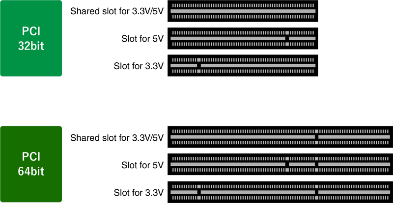
PCI bus
PCI (Peripheral Component Interconnect) is the bus interface standard for expansion cards. Data is transmitted in parallel on a 32-bit or 64-bit data bus width. Announced by Intel in 1992, it was soon widely adopted as the primary interface standard for expanding computer functions. Its successor, PCI Express bus, was introduced in 2003, and the PCI Express bus interface standard took over as the main interface standard. While no longer seen in consumer PCs, a broad range of periphery devices are used for industrial applications. Certain industrial computers still come with a PCI bus expansion slot to cater to these periphery devices.
PCI Express bus
PCI Express (Peripheral Component Interconnect Express) is the successor bus interface standard to PCI. Despite being its successor, PCI Express is not compatible with PCI, either physically or electrically. In contrast to PCI, PCI Express uses serial data transmission. Multiple serial transmission lines called “lanes” are used simultaneously to improve transmission speeds.
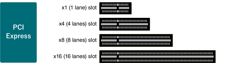
PCI Express bus compatibility (lanes)
PCI Express bus compatibility is based on the number of lanes as described in the table below. Note that expansion slots may differ in terms of their physical form and signals (lanes). For example, even if the physical form of the expansion slot is for an x16 card, an x16 card will operate in the performance range of an x8 card when inserted into slot with x8 signals. Note that some product combinations may not be built according to standard (incompatible), and will not function properly.
- Legend
-
- ◎: Can be installed/operates at the upper limit of expansion card performance
- 〇: Can be installed/operates within the signal range (number of lanes) of the expansion slot
- ×: Cannot be installed/does not function
PCI Express bus compatibility (version)
The PCI Express bus is upgraded (revised) while maintaining backward compatibility. For example, while a PCI Express 3.0 (Gen 3) expansion card will operate in a PCI Express 2.0 (Gen 2) expansion slot, the PCI Express 2.0 (Gen 2) performance range will be the upper limit of its performance. Note that some product combinations may not be built according to standard (incompatible), and will not function properly.
M.2
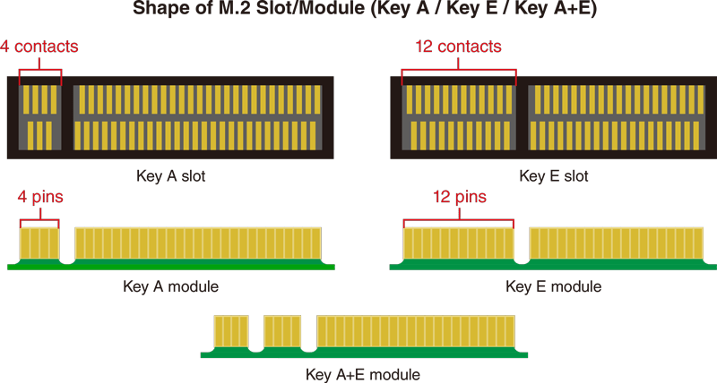
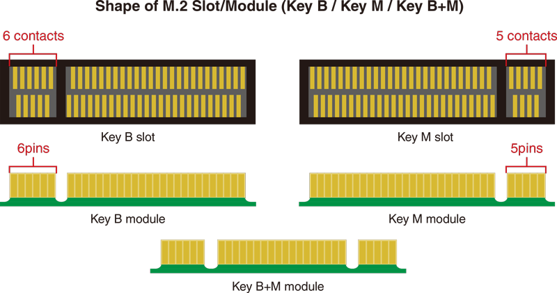
M.2 is a standard that determines the form factor and connection terminals of internal expansion modules in a computer. It is not a bus interface standard. It is positioned as a successor to mSATA, and has been called NGFF (Next Generation Form Factor). The M.2 module is accommodating on width and length, and the standard is best suited to smaller devices, such as laptops and tablets. The M.2 module is also applicable to industrial computers, where miniaturization is highly sought after, and the standard is becoming increasingly popular in this field. The four digit numbers included in specifications express the height and width (in mm).
In addition, there are different types of M.2 modules based on differences in the terminal shape (Key ID).
The motherboard layout of the BOX Computer BX-T210 features two M.2 sockets on the rear for installing an M.2 module. A Wi-Fi model equipped with a wireless LAN M.2 module is available as the standard product.
As with the BX-T210, the motherboard layout of the BOX Computer BX-M210 features two M.2 sockets on the rear for installing an M.2 module. A model with an isolated digital I/O M.2 module, and a model equipped with a SATA storage slot are available as standard products. Expanded function customizations available according to customer requirements.
To PageTop