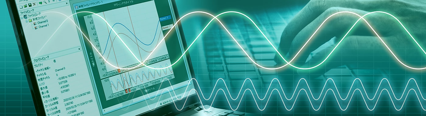
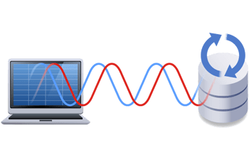
Why not use your laptop as a data logger?
We will show you how to combine Contec's USB analog input device with free data logger software, C-LOGGER, and use it as a data logger.
- Simply add an analog device to your PC to use it as a data logger.
- The data logger software C-LOGGER is available free of charge and the installation procedure is described here.
- Since the acquired analog data is stored on a PC, it is easy to use and has high affinity, including linking it to other software.
This article provides illustrated instructions on how to set up a PC to use it as a data logger.
Configuration of the system used in this article
■Features of the C-LOGGER Data Logger Software
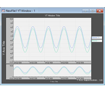
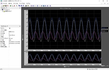
High-speed sampling and graphing
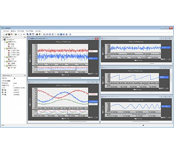
Multiple graph window display
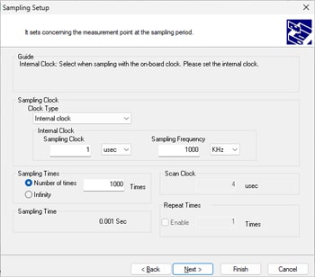
Interactive format (wizard) for
easy setting of sampling conditions
Function to customize data display graphs
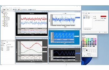
Function to customize data display graphs
Long time and large data collection by automatic saving
■Step 1 Device Setup
Device setup refers to the operations that must be performed before using a Contec device with a PC.
Preparations are required for both the software and hardware.
For this tutorial setup, we use the analog device "AI-1608GY-USB. "The screen display may differ depending on the product, but the basic procedure is the same.
If you have already completed the setup, see "Step 2: C-LOGGER Setup."
1.1 Installation of the software
Install software to run the device on your PC. The setup here is performed in Windows 11.The screen display may differ depending on the OS, but the basic setup procedure is the same.
Before connecting the analog device "AI-1608GY-USB" to your PC, download the device driver API-AIO(WDM) (hereinafter called “device driver”). Contec's device drivers are universal. The latest device driver is available here.
※
To download it, you need to register as a
myCONTEC member (free of charge).
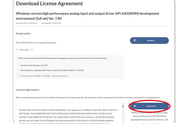 After reading and agreeing to the license agreement, click “Download” to download the software.
When downloading is complete, extract the downloaded file.
Open “<Destination folder>¥INF¥WDM¥AIO_ForWin10¥Setup.exe.”Execute “setup.exe” in the folder and follow the on-screen instructions to install the software.
-
※
Even though the folder is named “AIO_ForWin10,” it is compatible with Windows 11.
-
※
For customers who wish to use Windows 8.1/XP or earlier, please click
here.
-
※
The development environment is located in “<Destination folder>¥APIPAC¥AioWdm¥Disk1¥Setup.exe,” but it is not necessary to install this to use C-LOGGER.
-
※
If you want more details about how to install the device driver and development environment, please go to “
Online help> > Construction of Driver Environment > Installing Device Driver” for an illustrated explanation. Please take a look at them together.
1.2 Installation of the hardware
After completing the installation of the device driver, connect the analog device “AI-1608GY-USB” to the USB port of the PC to have the OS recognize it.
The device is installed automatically when the USB cable is connected to the PC.
If your device is a PCI Express (PCI) other than a USB, mount an expansion board while the PC is turned off.
For details about how to install device drivers, please refer to “Online help > Driver Building Environment > Device Driver Installation.”
Confirm that the device has been installed correctly.
Right-click on the Start button and open Device Manager.
The installed device is displayed under the Contec Device tree.
Attachment to prevent connector disconnection
To prevent accidental disconnection of the USB cable, an attachment is included to prevent connector disconnection. Be sure to make use of it.
1.3 Connection and operation check with external devices
Let’s conduct a simple test to see if we can get an analog signal. This explanation is based on cases where a function generator is connected. The function generator outputs a sine wave of 10 Hz and 5 [V] amplitude as an example.
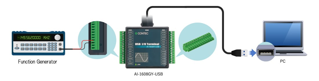
Connect AI00 and AGND to the signal source.
Signal names are printed for easier signal wiring.
AI00 to AI07 are all analog input channels and AGND is analog ground.
Convenient to have multiple terminal connectors
The terminal connector (model: CN6-Y14) is detachable and can be replaced.
Preparing several pre-wired terminal connectors according to the measurement pattern would be convenient as this means that they do not need to be rewired and can be simply replaced.
This is useful because it also helps to prevent wiring errors.
1.4 Operation check with diagnostic program
Let's confirm the actual waveforms on a PC. The process here is not to acquire data, but to confirm if the analog signal can be acquired correctly.
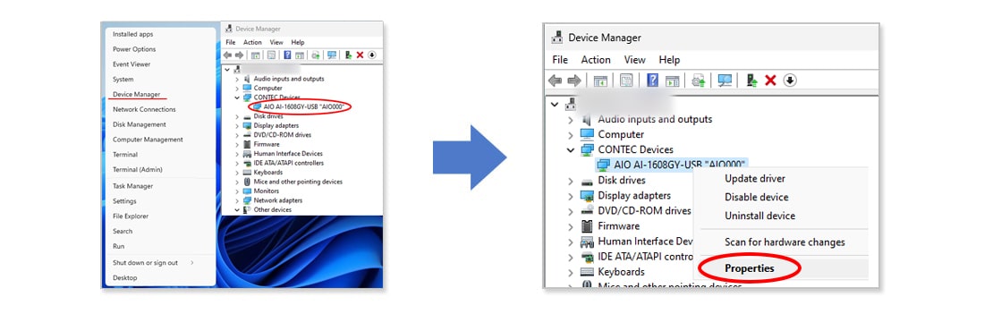
Right-click on the Start button and open Device Manager.
The installed device is displayed under the Contec Device tree.
Right-click on the device you want to confirm (in this case, AIO AI-1608GY-USB “AIO000”*)and select →Properties (R).
Click Common Settings.
“Device Name” is a name assigned by our product to identify the device.
The software calls it by this name.
You are free to change it or leave the default name as it is.
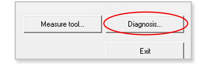
The diagnostic program is activated by clicking the Diagnosis button in the lower left corner of the Common Settings window.
In the diagnostic program, graphs of analog inputs and input data can be used to confirm the input of the relevant signals.
Confirm that the analog input signal has been correctly acquired.
Maximize the data collection speed in the upper right corner and confirm that a ±5 V sine wave is displayed.
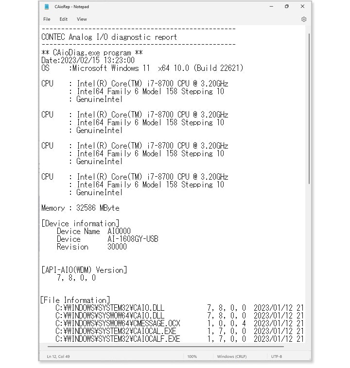
■Diagnosis report function■
Clicking the “Diagnosis Report” button outputs the settings information, installed driver version, and self-diagnostic results in a text file.
Since the information we ask for in technical support can be automatically retrieved, please attach a text file of the diagnostic results to your question so that we can answer it more smoothly.
< p="" class="image-inner" />
This completes the preparation for acquiring analog data with the device.
The next step explains how to install the free data logger software, C-LOGGER.
Forward to Step 2
C-LOGGER Setup