This section explains aspects of digital input and output, from applications and types to interface circuit characteristics, in an easy-to-understand way.
Contents
1. What is a Digital I/O Board?
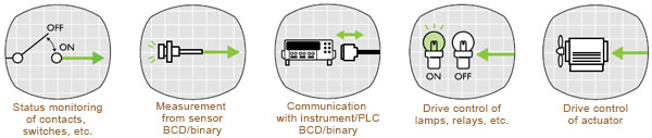
A digital I/O board is an interface board that adds the ability to input and output digital signals in parallel to a computer. Using a digital I/O device makes it possible to monitor (read) the statuses of measuring devices as well as the relays and operation switches of various types of control circuits. In addition to controlling output for lamps, LEDs, 7-segment displays, and relays, such products can also be used as an interface for digital communication with controllers such as a PLC (sequencer).
2. Digital I/O Board Types And Applications
2-1. Photocoupler-isolated I/O type
This type provides isolation of the I/O circuit and the logic circuit inside the board using a photocoupler. Transmitting a signal (information) using light makes it possible to prevent the effects of electrical disturbances generated in the operation circuit. However, an external DC power source is required to drive the photocoupler. This is used for connecting the operation circuit to weak electrical devices using 5 to 48 VDC, such as digital switches and indicators.
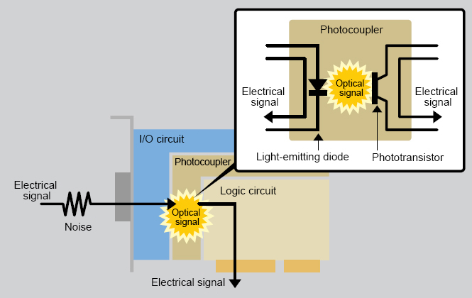 Isolation of the I/O circuit and the logic circuit inside the board using a photocoupler
2-1-1. High-speed photocoupler-isolated I/O type
This type enables faster signal transmission speeds by using a high-speed photocoupler as the isolating element. This type is used when high-speed input and output is required.
2-1-2. High-speed photocoupler-isolated I/O type with built-in power source
This internal logic circuit is equipped with an isolated DC power source. Because power is supplied to the photocoupler's drive and operation circuits, this type is useful when power cannot be provided.
2-2. Contact output type
This type uses a relay in the output circuit. The logic circuit and output circuit inside the board are isolated by this relay contact. Also, because there are no limits on the direction the current flows, AC (alternating current) loads can also be connected. Use this type with AC operating circuits or to directly control strong electrical devices using more than 48 VDC.
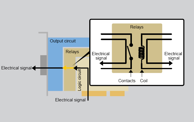 Relay used in output circuit
2-3. Non-isolated I/O type
This type features a direct connection of the logic circuit inside the board and the I/O circuit without isolation. Compared with photocoupler-isolated I/O types, this type offers high-speed responses. However, because it is susceptible to electrical disturbances, this type is suitable for environments with favorable noise characteristics and when wiring distances can be shortened. Use this type for devices with 5 VDC / 3.3 VDC I/O circuits and TTL/LVTTL devices, including small relays and controllers.
Direct connection of the logic circuit inside the board and the I/O circuit without isolation
2-3-1. Bidirectional I/O type
This type features a direct connection without isolation between the logic circuit inside the board and an i8255 PPI or equivalent bidirectional I/O circuit. Using a program allows the number of inputs and outputs to be changed in 8-point units. Use this type of product when connecting to equipment that requires TTL (5 VDC) or LVTTL (3.3 VDC) bidirectional I/O.
3. Output Circuit
Output circuits for digital input and output are categorized into the following types according to application and electrical differences.
3-1. Transistor output (contact-less output)
Using a transistor that functions as a semiconductor device, this output circuit is capable of driving and opening/closing DC loads. This type of output is called contact-less output because there is no real contact involved, unlike contact output.
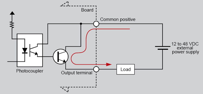
3-1-1. Photocoupler-isolated open-collector output (current sink type)
This output circuit is where the output transistor collector becomes the output terminal and the status becomes open. The internal logic is "ON (short): 1, OFF (open): 0." In this sink type, when the output transistor becomes "ON" (a load is operated), the current flows from the load to the output terminal. This output is used to send signals to typical weak electrical devices using 12 to 48 VDC.
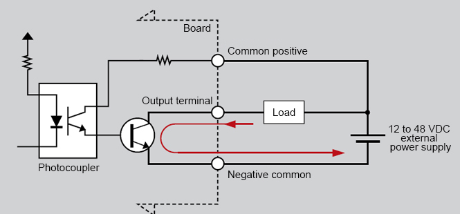 Output circuit where the output transistor collector becomes the output terminal and the status becomes open
3-1-2. Photocoupler-isolated output (current source type and negative common type)
In this output circuit, the output transistor emitter becomes the output terminal. The internal logic is "ON (short): 1, OFF (open): 0." In this source type, when the output transistor becomes "ON" (a load is operated), the current flows from the output terminal to the load. This output is used to send signals to weak electrical devices using 12 to 48 VDC and is the preferred source type in European countries because it offers high safety concerning ground faults.
 Output circuit where the output transistor emitter becomes the output terminal
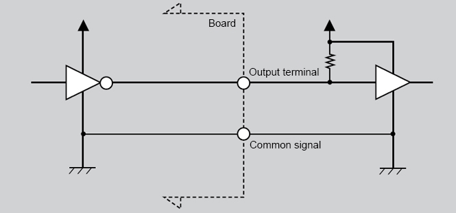
3-1-3. Non-isolated TTL open-collector output (negative logic)
With this output circuit, the output transistor collector becomes the output terminal, the status is open, and the input circuit side is pulled up. The internal logic is negative logic of "Low (short): 1, High (open): 0." This output is used to send signals to devices with TTL input circuits and 5 VDC devices.
 Output circuit where the output transistor collector becomes the output terminal and the status is open
3-1-4. Photocoupler-isolated TTL level output (negative logic)
In this output circuit, the output transistor collector becomes the output terminal. The internal logic is negative logic of "Low: 1, High: 0." This output is used when the operation circuit wiring of devices with TTL input circuits and 5 VDC devices becomes too long or to isolate such devices.
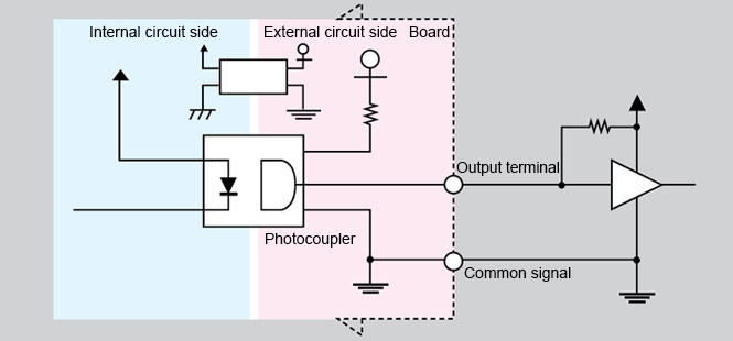 Output circuit where the output transistor emitter, isolated by a photocoupler, becomes the output terminal
3-2. Contact output (reed output)
This output circuit, which uses a relay contact, is isolated with the internal logic circuit. The circuit is also called a reed output because, using real contact, it drives and opens/closes the load. Also, because there are no limits on the direction the current flows, AC (alternating current) loads, as well as DC loads, can be connected. This output is used with alternating currents (AC) or to send signals to strong electrical devices using more than 48 VDC.
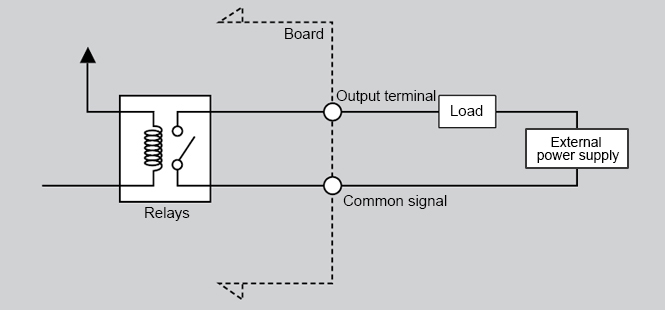 Output circuit isolated with internal logic circuit using relay contact
4. Input Circuit
Input circuits for digital input and output are categorized into the following types.
4-1. DC input
This input circuit can be connected to such contact output circuits as DC transistor outputs or DC operation circuits.
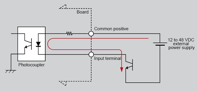
4-1-1. Photocoupler-isolated input (type compatible with current sink output)
This is the input circuit with the cathode side of the photocoupler as the input terminal. This input is used to receive output signals from such sources as sink-type transistor outputs and relay switches. The internal logic is "ON (short): 1, OFF (open): 0." The input terminal is a source-type terminal that feeds an electrical current. This type is used to input signals from typical weak electrical devices using 12 to 48 VDC.
 Input circuit with photocoupler cathode side as input terminal
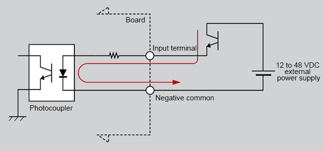
4-1-2. Photocoupler-isolated input (current source output-compatible type and negative common type)
This is the input circuit with the anode side of the photocoupler as the input terminal. This input is used to receive output signals from such sources as source-type transistor outputs and relay switches. The internal logic is "ON (short): 1, OFF (open): 0." The input terminal is a sink-type terminal that accepts an electrical current. This is the preferred type in European countries because it offers high safety concerning ground faults. This type is used to input signals from weak electrical devices using 12 to 48 VDC.
 Input circuit with photocoupler anode side as input terminal
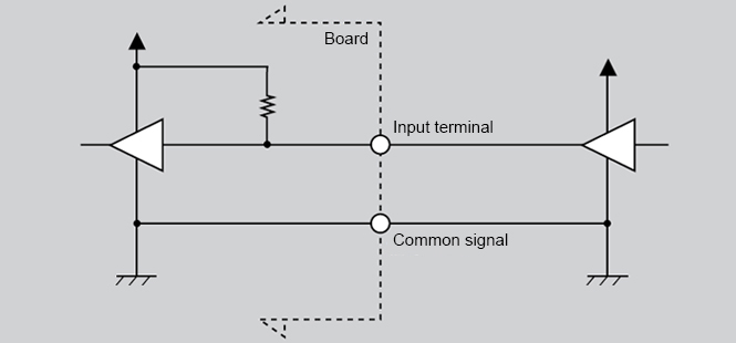
4-1-3. Non-isolated TTL level input (Negative logic)
With this input circuit, pulled up at 5 VDC, the transistor base becomes the input terminal. The internal logic is negative logic of "Low: 1, High: 0." This type is used to input signals from devices with TTL output circuits and 5 VDC devices.
 Input circuit pulled up at 5 VDC with the transistor base as the input terminal
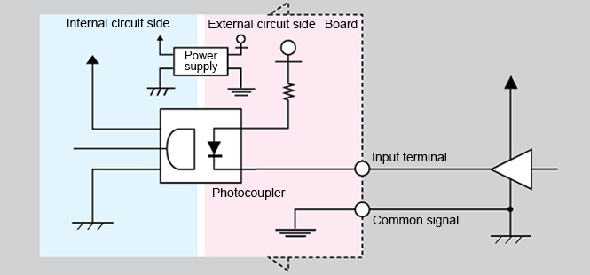
4-1-4. Photocoupler-isolated TTL level input (negative logic)
This is the input circuit with a photocoupler cathode as the input terminal. The internal logic is negative logic of "Low: 1, High: 0." This input is used when the operation circuit wiring of devices with TTL output circuits and 5 VDC devices becomes too long or to isolate such devices.
 Input circuit with photocoupler cathode as input terminal
5. Bidirectional I/O Circuit
5-1. Non-isolated TTL/LVTTL level input/output (positive logic)
This is the i8255 PPI (or equivalent) I/O circuit. The internal logic is positive logic of "Low (short): 0, High (open): 1." Use this type of product when connecting to signal inputs/outputs from equipment with TTL I/O circuits, 5 VDC equipment, or equipment that requires TTL (5 VDC) or LVTTL (5 VDC) bidirectional I/O.
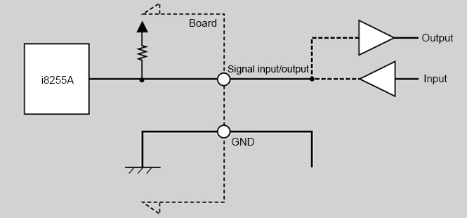 i8255 PPI (or equivalent) I/O circuit
6. Selection Hints
CASE 1 Performing relay control at the digital output board
With ON/OFF relay control, the number of devices usually becomes the number of outputs needed. To control 10 relays, select a board with 10 or more outputs.
-
※
The device you are using may offer such functions as alarms, resetting, and handshaking. In such instances, it is necessary to supply the appropriate number of additional inputs/outputs.
CASE 2 Monitoring switches at the digital input board
When monitoring the ON/OFF status of switches, the number of devices usually becomes the necessary number of inputs. To monitor 20 switches, select a board with 20 or more inputs.
-
※
The device you are using may offer such functions as alarms, resetting, and handshaking. In such instances, it is necessary to supply the appropriate number of additional inputs/outputs.
CASE 3 Controlling a 7-segment display with BCD/binary data input from the digital output board
CASE 4 Inputting BCD/binary data from the digital switches at the digital input board
With typical decimal and hexadecimal types, usually 4-bit (4-point) output and input is needed for 1 digit. With 3-digit, 7-segment display devices or digital switches, select a board with at least 12 inputs and outputs (4 points × 3 digits).
-
※
The device you are using may offer such functions as alarms, resetting, and handshaking. In such instances, it is necessary to supply the appropriate number of additional inputs/outputs.
CASE 5 Absolute-type (binary data output) rotary encoder
In general, the number of inputs is related to the resolution for one revolution. For example, for a resolution of 256 in one revolution, 8-bit (256=28) binary data will be output. Select a board with 8 or more inputs.
-
※
The device you are using may offer such functions as alarms, resetting, and handshaking. In such instances, it is necessary to supply the appropriate number of additional inputs/outputs.