Analog Measurement Techniques for On-Site Technicians
With analog signal measurement, selecting an analog input interface and peripheral accessories suitable for the frequency of the target signal is essential. Cables, buffer amplifiers, and other accessories must be carefully selected to ensure the signal is acquired correctly.
Recommended sampling rate: 10 times the frequency being measured
The first step in measuring an analog signal is to determine the sampling rate (period). A faster sampling rate provides greater accuracy when converting the original signal waveform into a digital signal. However, as the sampling rate increases, the amount of data also increases, resulting in the need for more expensive A/D converters in the analog input interface.
To determine a realistic index, the sampling theorem should be considered first. The sampling theorem specifies the interval at which a continuous analog signal should be sampled into a discrete digital signal. To sample all the frequency components in the original signal accurately, the sampling rate must be at least twice the frequency of the original signal.
For example, accurate sampling of a 1 kHz analog signal requires a sampling rate of at least 2 kHz. Anything less will prevent accurate sampling of the frequency components in the original signal. When sampling at low speeds, a high-speed signal will appear as a folded signal, resulting in aliasing and causing the signal waveform to appear as a lower frequency than the actual original waveform frequency.
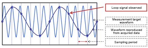
Aliasing is something that can be observed in our daily lives. For example, a propeller rotating at a high speed appears slow because the sampling rate of our eyes and brain cannot keep up with the frequency of the rotating propeller. If aliasing occurs, the sampling result will look significantly different from the actual signal frequency.
Following the sampling theorem should ensure that the frequency components are accurately acquired. In reality, however, the waveform will look jagged and a sufficient amplitude will not be acquired if the sampling rate is only twice the frequency of the original signal. To ensure the signal characteristics are captured accurately, a sampling rate of at least 10 times the frequency of the original signal is recommended. Contec provides various analog input interfaces for specific frequencies.
Acquiring data at the same sampling rate
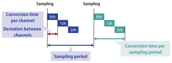
When using an analog input interface to measure multiple signals, the signals from all measured channels are not necessarily sampled at the same rate. If the analog input interface includes enough A/D converters to cover all channels, the analog signals of all channels can be synchronized and sampled at the same rate.
With multiplexer models, however, the channels are switched by the multiplexer and sampled using a single A/D converter. This means that the sampling period for each channel will increase depending on the number of channels, and a gap will be generated in the sampling rate between channels.
|
Simultaneous sampling models
|
Multiplexer models
|
|
|
|
Even with multiplexer-based analog input interfaces, time discrepancies can be eliminated by using a simultaneous sampling function extension accessory. The ATSS-16A can acquire data at the same sampling rate with no time discrepancy by holding the analog input signals of 16 channels simultaneously according to the control signal from the Analog E series.
Removing noise
Noise can generally be categorized into external or internal noise. Unlike with electrical testing, various on-site noises can cause unexpected results that do not conform to theory. In such situations, noise will be the driving factor behind any accuracy deviations.
External noise
- Airborne noise from outside the signal transmission line
- Noise from power system wiring such as motors, or noise from nearby wiring
Internal noise
- Crosstalk between signal lines
- Crosstalk caused by multiplexer switching
- Noise caused by ground loops (earth loops)
Reducing noise using hardware
Measures for preventing noise can be software-based, such as with averaging, or hardware-based applied through cables and accessories.
Removing airborne noise
One effective way to remove airborne noise is to connect the analog input interface to the measurement target using a shielded cable. Such cables remove noise because the shielding is grounded through the PC frame, resulting in the cable being grounded with the PC’s power supply.
Eliminating crosstalk between signal lines
Crosstalk is what happens when signal lines interfere with each other, resulting in noise. Using twisted pair cable is an effective way to prevent crosstalk. Contec’s PCB37PS shielded cable includes a signal line and a ground line in a twisted pair, while the PCB96PS includes a twisted pair between differential pairs. The PCC16PS and PCD8PS are also available with coaxial cable signal lines.
Eliminating crosstalk caused by multiplexer switching
The switching of the multiplexer in the analog input interface can affect the signal source waveform. This phenomenon is caused by the charging and discharging of the stray capacitance of the multiplexer via the output impedance of the signal source. With a higher signal source output impedance, the output voltage of the signal source will take longer to return to the desired measurement voltage (known as the settling time).
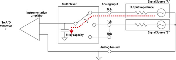 Example input circuit of an analog input interface
The settling time will vary depending on the signal source output impedance. The following is an example of sampling with two channels: signal source A, which has a low output impedance, and signal source B, which has a high output impedance.
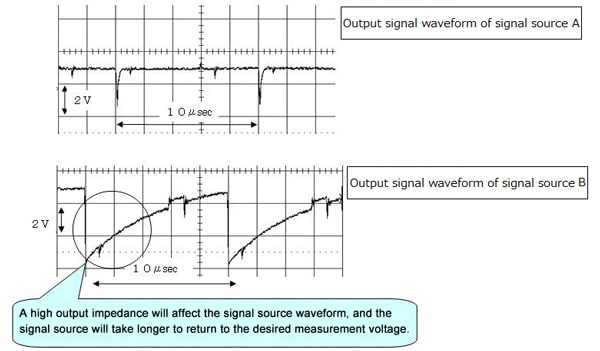
Reducing the signal source output impedance is an effective way to prevent the effects of multiplexer switching. In particular, the signal line should be as short as possible. If the signal line cannot be shortened, or if the target has a high output impedance, multiplexer switching effects can also be prevented by connecting a buffer amplifier with a high input impedance as well as a high-speed, high-precision operational amplifier.
Eliminating errors caused by ground loops (earth loops)
A ground loop, or earth loop, occurs when the ground wiring becomes looped. In a system with multiple connected devices, there may be an electric potential difference between the grounds (GND) of each signal, causing the current to flow in a loop through the ground wiring. When current flows through this ground loop, voltage will be generated depending on the path impedance, and this voltage will appear as a measurement error (noise).
Single-ended input (common mode) is useful when handling a large number of channels, but this input type is affected by ground loops. On the other hand, differential input (differential mode) has half the number of channels of single-ended input and is not affected by ground loops.
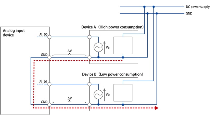
Example of errors caused by ground loops
- Single-ended input
- Measurement voltage of AI_00 = Va + ΔV
- Measurement voltage of AI_01 = Vb - ΔV
- With single-ended input, the current flowing through the ground loop causes a measurement error of ΔV.
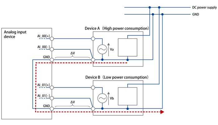
- Differential input
- Measurement voltage of AI_00 = (Va + ΔV) – ΔV = Va
- Measurement voltage of AI_01 = (Vb – ΔV) – (-ΔV) = Vb
- With differential input, the voltage between the positive (AI_00[+]) and negative (AI_00[-]) terminals can be measured to eliminate errors caused by the ground loop.
This makes differential input an effective way to prevent ground loop-related errors. If a ground loop is suspected, using bus isolation to cut the ground loop might be useful.
Related Links
See All Blogs