Contents
What is EtherCAT?
EtherCAT (Ethernet for Control Automation Technology), which has been garnering attention since its full adoption by Toyota Motor Corporation in 2016, is an open field network with real-time capability developed by Beckhoff Automation. Currently, function requirements and certification procedures are specified and managed by the EtherCAT Technology Group, which was founded in 2003.
What is a field network?
A field network is a network for communicating with controller and measurement devices such as sensors in factories. Among field networks, those that use Ethernet networks are called industrial Ethernet. Industrial Ethernet includes Profinet, Ethernet/IP, CC-Link/IE Field, Modbus/TCP, etc. and EtherCAT is also an example of industrial Ethernet.
EtherCAT communication example
EtherCAT divides devices into master and slave, with one or more slave controllers connected to a single master. They can be connected by daisy-chain or star topology.

During communication, data for all slaves is sent in a single packet. In the above example, the packet data would be as follows.
The size and function of the device data are described in the EtherCAT Slave Information file, and the EtherCAT master uses this information in advance to create the packet data as shown above.
Data is transferred in order from the slave controller closest to the master. The blue arrows (1) through (6) indicate the order of EtherCAT packet data transfer. In the case of the above connection, the data for that device is updated from (1) to (3) in order from the beginning. For input data, the packet is updated, and for output data, the device is updated to the value of the data. After reaching the end Slave 3, turn around and return in the direction of the arrow from (4) to (6), and update the input data, and then finally the master receives it.

EtherCAT redundancy
If multiple LAN ports are available on the master, EtherCAT can be duplicated by looping the connection. Since CPS-PC341EC-1-9201 will not allow LAN communication when two LAN ports are assigned to EtherCAT, the following is an example of a connection using a PC with two or more LAN ports equipped with a software PLC.

In this case, communication is performed in two directions, blue and green, respectively. The orders are, blue arrows (1) through (4) for LAN port 1 transfers, and green arrows (1) through (4) for LAN port 2 transfers.
When duplicated, communication can continue without interruption even in the event of a disconnection on the route. It also clearly shows its location. The following diagram shows the case of a disconnection between Slave 2 and Slave 3. Because communication is disabled at Slave 2, after communication from LAN port 2 reaches Slave 3, it returns to the master, and communication is performed only with Slave 3 as shown in green arrows (1) and (2). LAN port 1 communication with the blue arrow proceeds to Slave 2 and then returns to the master because communication is disabled at Slave 3. Blue arrows (1) through (4) are for LAN port 1 communication.

Compatibility issues with EtherCAT products
EtherCAT products have a variety of master and slave devices. In some cases, not all functions operate normally on a PC with EtherCAT Master software installed or on a master product and an EtherCAT slave product. The EtherCAT Technology Group conducts annual connection tests for EtherCAT master and slave developers to eliminate compatibility problems as much as possible.
Contec’s CONPROSYS PAC Series is deploying EtherCAT master and slave products, and we have confirmed that they work properly in combination with the PAC Series, so you can use it with confidence. In addition, we offer an evaluation device lending service for those who want to use Contec slave products with non-Contec masters, or who are not sure if non-Contec slaves and Contec master products will operate normally, or who want to check the operation of Contec devices before purchasing them. We highly recommend it.
What is a PLC?
Install a system that utilizes PLCs and software when you want to program an EtherCAT master, such as controlling sensors or acquiring their status via EtherCAT communication. PLC is an acronym for Programmable Logic Controller, also called a sequencer. These controllers can control sensors, LEDs, and other control devices on a logic-by-logic basis. Hardware PLCs are dedicated devices that are specialized for logic processing and are mainly equipped with microcontrollers. Software PLCs are systems in which PLC functions are installed in an industrial computer, etc., to perform a wide range of processing. Contec’s PAC Series uses the software PLC CODESYS.
What is CODESYS®?
Developed by CODESYS GmbH, CODESYS® is a software PLC that complies with the international standard IEC 61131-3. Five languages defined by IEC 61131-3 are supported. Products with CODESYS implemented can act as EtherCAT masters. CODESYS software is handled by LINX Corporation and can be downloaded free of charge here(Japanese). (User registration is required for both CODESYS and LINX.)
Differences between PC programming and CODESYS PLC programming
As an analogy, when programming in Python or other languages on a PC, there is a start and the process moves toward a predetermined goal, but in the case of CODESYS programming, the process goes around a track many times according to a predetermined cycle time.
[An analogy of PC programming]

[An analogy of CODESYS programming]

In PC programming, a thread called a timer thread that runs at a predetermined time can be used. However, when it comes to milliseconds to microseconds, time fluctuations occur, and it is difficult to keep the thread running at 1 millisecond intervals, and it is often the case that the thread is off by around 10 milliseconds. With CODESYS, milliseconds or hundreds of microseconds can be set, depending on the device. However, care must be taken when programming PLCs. For example, when programming on PC, you can wait (e.g., sleep), but CODESYS programming requires continuous execution with a predetermined cycle time, so you must program in such a way that you ‘process in the next cycle,’ rather than wait.
CODESYS® programming language
The five PLC programming languages defined in IEC 61131-3 are: Ladder Diagram (LD), Instruction List (IL), Function Block Diagram (FBD), Description Language Sequential Function Chart (SFC), and Structured Text (ST). CODESYS can be written in the PLC programming languages defined in IEC 61131-3.
EtherCAT communication control using CONPROSYS PAC Series
Choosing a product
Contec offers the CONPROSYS PAC Series with CODESYS as a device with software PLC functions. CONPROSYS PAC controllers are equipped with CONPROSYS HMI as a human interface, allowing visualization of data collected by CODESYS from EtherCAT slave devices.

There are EtherCAT master products CPS-PC341EC-1-9201 and CPS-PCS341EC-DS1-1201, EtherCAT slave coupler CPS-ECS341-1-011—an EtherCAT slave product that can be expanded with up to 16 modules—and the IO-Link gateway CPSL-08P1EN which can connect up to 8 IO-Link sensors. Below is a product category chart.
[Product category chart]

Example of CODESYS programming
In this example, after the CODESYS development environment is installed in the following configuration, the HMI monitors the analog current with EtherCAT communication and goes as far as turning on the digital output when the current value drops to a threshold value.

CODESYS programming beginner’s guide
Key points! Once the initial setup of the configuration and connection information is done, programming is a snap!
Installation of PAC controller and EtherCAT configuration information
First, install the library for the PAC controller, CPS-PC341EC-1-9201. Download the CPS-PC341EC-1-9201 library here. Start installation from the package manager.

Next, install the ESI file (EtherCAT Slave Information file), which contains the EtherCAT configuration information. Download the ESI file for CPS-ECS341-1-011 here. Start installation from the device repository.

Project creation and programming language selection
Next, create a project.
We will select Structured Text (ST), a language that allows programming similar to C and other languages.

EtherCAT connection setting
Add an EtherCAT master to the controller. After adding the EtherCAT master, configure the device settings for CPS-ECS341-1-011. In this case, we are connecting a digital output and an analog input device, so we register those two devices. After registering the setting, register the analog input terminal (AnalogInput0) and digital output terminals (DigitalOutput0, DigitalEchoOutput0) to be used.

This completes the preparations.
Program
Code the PLC_PRG in the programing screen. There is an instruction declaration section and a program section, which is programmed using the declared variables and the terminals registered in step 3.
Variable declaration section
VAR
// Variable registered in HMI
threshold :LREAL:= 0.0;// Threshold (mA)
value : LREAL := 0.0;//Current value (mA)
lump0 : BOOL := FALSE; // Confirmation value of digital output (Echoback Input value)
// CPS-AI-1608ALI device
max_current : LREAL := 20.0; // Maximum value (mA)
resolution : LREAL := 65536.0; // Resolution 16 bit -> 2 to the power of 16
END_VAR
Program section
value := (AnalogInput0 * max_current) / (resolution – 1.0); // Conversion to mA
if (value < threshold ) then
DigitalOutput0 := TRUE;
else
DigitalOutput0 := FALSE;
end_if
lump0 := DigitalEchoOutput0;
When programming EtherCAT libraries on a PC, it is necessary to program the reading of ESI files, EtherCAT communication exchanges, and message communication exchanges for parameters called object dictionaries. With CODESYS, the programming for the EtherCAT communication can be omitted because the CODESYS library does it for you, and you can easily operate analog input devices and digital output devices directly.
Register the variables ‘value’ and ‘threshold,lump0’ for use with CONPROSYS HMI.
For this, add symbol configuration.

After adding, check the variables you want to use and press the build button again to complete the process.

This program will disappear when the CPS-PC341EC-1-9201 is turned off, so access the unit from a web browser to save the program.

Linking with CONPROSYS HMI
Key points! Just create a monitoring screen, place the parts, and link the variables registered in CODESYS, and you’re good to go!
Perform monitoring editing.
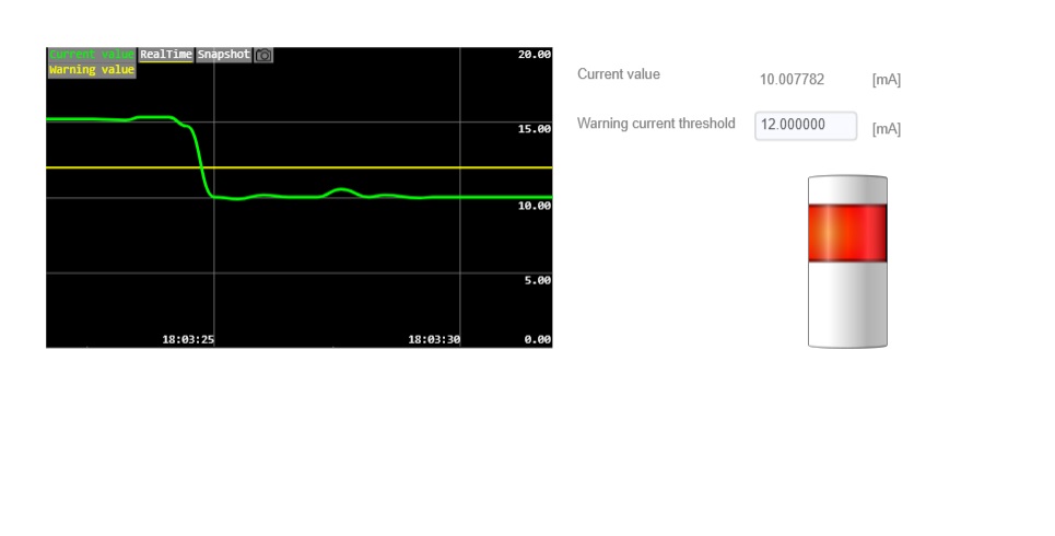
Trend graphs are used for current values and thresholds, and tower lights are used to check digital outputs. Stick the parts to display the current value in a label and the threshold value in a text box. Below is the creation screen.
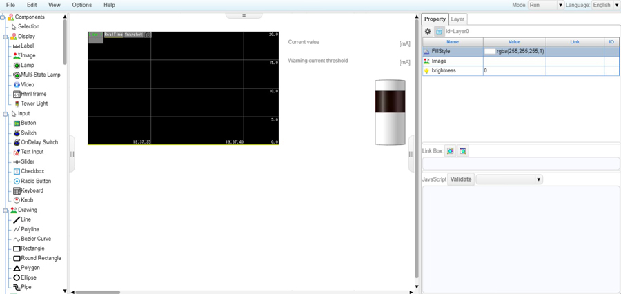
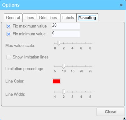
This time, the tower light setting is used only on the top row. Also, the Y-axis scale of the trend graph has been fixed to 20 for the maximum value and 0 for the minimum value.
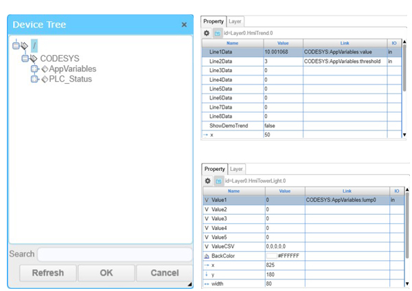
Associate variables (value, threshold, lump0) registered in CODESYS.
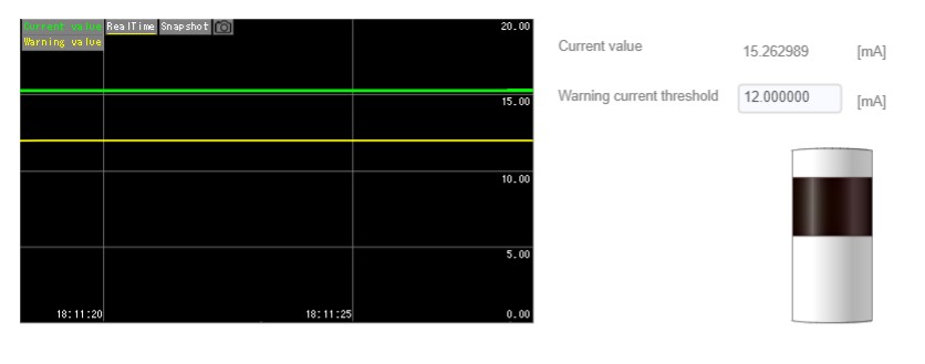
All that remains is to save it, and then it is ready to use. If the current value is below the threshold, the tower light turns on in red after the digital output is turned on. Below is the CONPROSYS HMI when threshold is set to 12 mA.
What did you think? Control programs using EtherCAT communication can be easily created using this method. This description was limited to controlling EtherCAT, but there are various other functions such as file saving and cloud transmission of the PAC controller that can be linked. If you want to create such a program, we have prepared a reference guide (software) and sample programs as part of the detailed documentation.
Related Link
See All