In a previous article, we explained why the selection of analog input interface and peripheral accessories is important for analog signal measurement. This time we focus on cables for peripheral accessories and explain ways to improve analog signal accuracy.
Contents
The Need for Noise Countermeasures
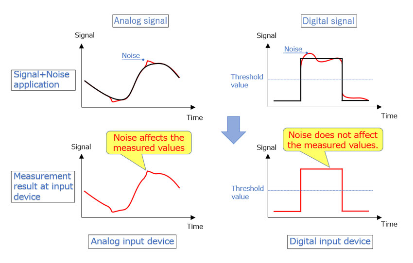
Noise can intrude by a variety of routes. Noise can act on the signal measurement device and measurement target device, and it can also act on the cables which connect the devices. In the case of a digital signal, there are two values: 1 and 0. Even when noise is applied, the result on the digital input interface side will not change as long as the noise does not exceed a certain threshold value.
However in the case of an analog signal, when noise creates distortion in the signal, the signal containing the distortion is applied directly to the analog input interface side. Because noise can cause a decline in signal quality, noise countermeasures are necessary in order to perform accurate signal measurement.
Shielded Cables: Eliminating Airborne Noise
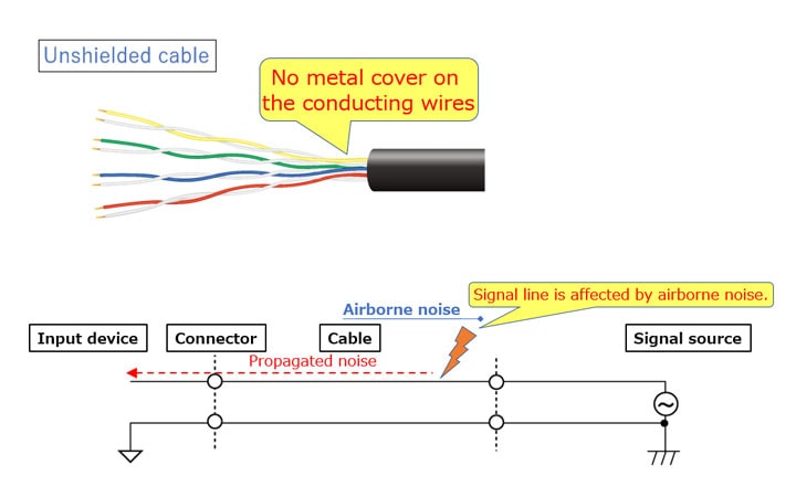
A cable can function as an antenna and receive airborne noise that travels through space in the form of unwanted electromagnetic waves.
The received noise is applied to the measured signal, decreasing measurement accuracy.
One effective way to remove airborne noise is to connect using a shielded cable.
Shielded cables
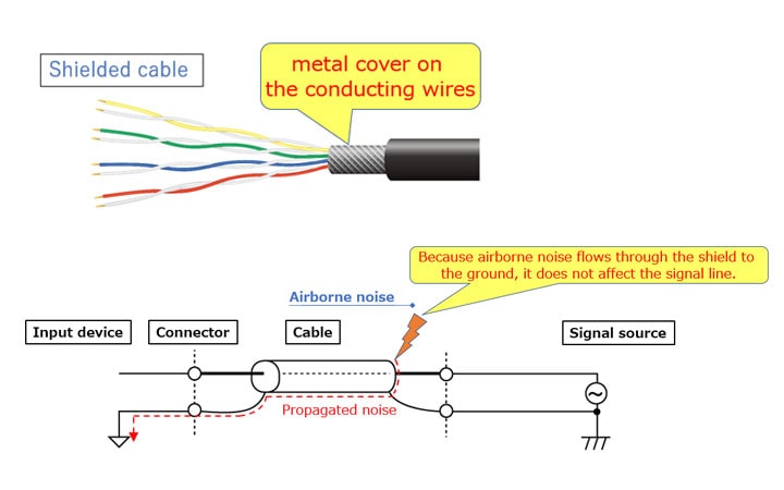
A shielded cable is a cable in which the signal line is covered by a metal shield. The shield is composed of braids or foil made from a material such as copper or aluminum.
Shielded Cables: Eliminating Airborne Noise
Airborne electromagnetic noise can be absorbed by the covering metal braids or foil, and discharged via a grounded FG. This prevents the electromagnetic waves from interfering with the signal line.
When grounding the shield, grounding only one end of the cable and leaving the other end free may improve signal stability. The reason is that when both ends are grounded, this creates a large ground loop between the devices, and makes it more likely that common mode noise will be picked up via the ground.
Recommended shielded cables
Contec provides a variety of instrumentation card cables and accessories that include noise countermeasures.
You can select the ideal shielded cable with consideration for a wide range of methods for connecting to the opposite device.
The cables for each product can be selected from the page below, however here we will introduce some of our recommended shielded cables.
| Cable model |
Photo |
Overview |
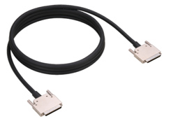
| PCB96PS |
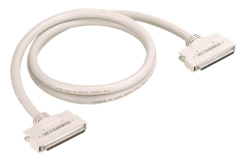 |
This is a shielded cable that can be used with the analog F series. The pair of wires for the differential signal are a twisted pair, producing a cable that is highly resistant to noise when a differential signal is input.
|
| PCB68PS-P |
 |
This is a shielded cable that can be used with the analog L series (64 ch input). The pair of wires for the differential signal are a twisted pair, producing a cable that is highly resistant to noise when a differential signal is input.
|
| PCB37PS |
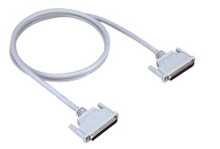 |
This is a shielded cable that can be used with the analog E series. The signal wires between each input channel signal and GND are a twisted pair, producing a cable that is highly resistant to noise for single-ended input.
|
Twisted Pair Cables: Canceling Airborne Noise
Twisted pair cables (TP cables)
Twisted pair cables are cables in which the pair of signal wires is twisted together in a helix.
Canceling airborne noise with twisted pair cables
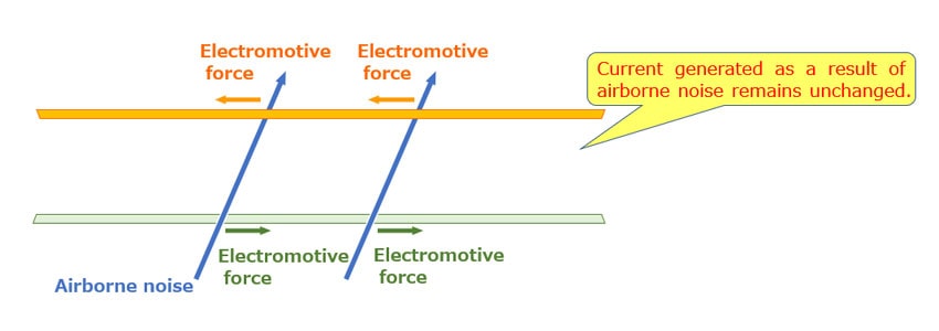
If the signal wires are parallel to each other, then when electromagnetic waves of airborne noise create a magnetic field, the field will produce an electromotive force. This force generates an induced current that becomes a source of noise.
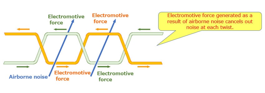
As a countermeasure, the signal wires are twisted together, causing the direction of the electromotive force to reverse at each twist.
As a result, the electromotive force cancels out the noise, reducing the effects of airborne noise.
Comparison of Noise Resistance by Cable Type
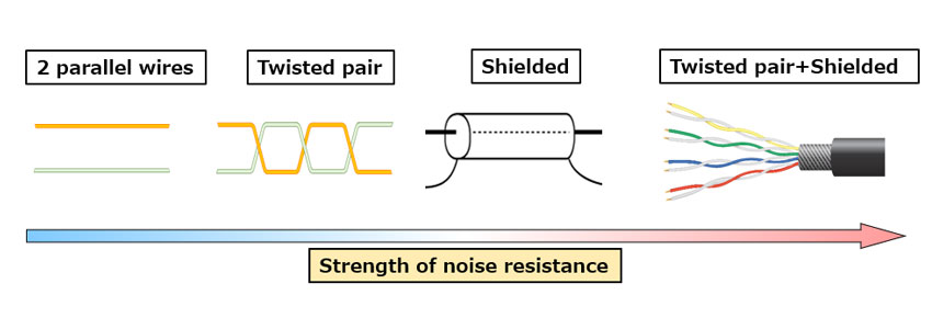
The effectiveness of each cable type against noise is as shown in the figure below.
The cable with the lowest noise resistance contains two parallel wires, and is defenseless against both induction noise and electrostatic noise.
Next is the twisted pair cable. It is able to reduce induction noise, however it is defenseless against electrostatic noise.
Next is the shielded cable. It is able to reduce electrostatic noise, however it is defenseless against induction noise.
The cable with the highest noise resistance is a cable that combines a twisted pair cable with a shield. It includes countermeasures to both induction noise and electrostatic noise.
Cable Length: Countermeasures to Voltage Drop and Waveform Distortion
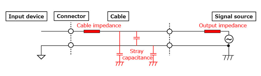
A CR circuit is formed as a result of sensor output impedance or as a result of the cable impedance component and stray capacitance.
This means that when the cable length increases, voltage drop and waveform distortion occur in the output signal.
Selecting the shortest possible cable length (around 0.5 to 1.5 m) can reduce these effects.
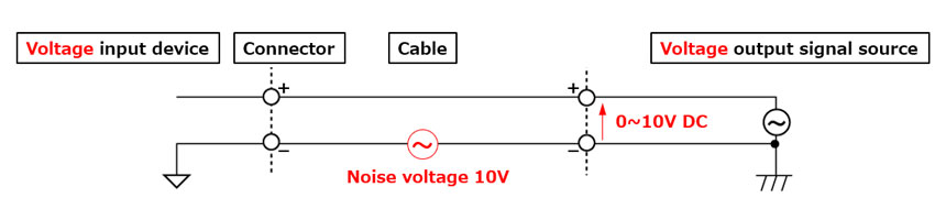
In order to transmit a signal over long distances without being affected by noise, a current signal can be used instead of a voltage signal.
In a measurement environment with a voltage signal of 0 to 10 V, when 10 V is applied as noise voltage, the receiving device is affected equally by the noise voltage and the signal voltage.
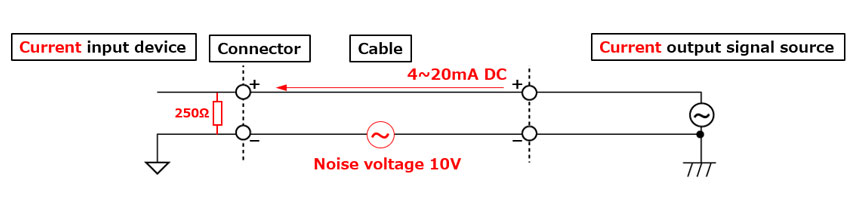
However in a measurement environment with a current signal of 4 to 20 mA, the effects when 10 V noise voltage is applied are different.
The resistance value of the signal source as viewed from the output terminal of the current output signal source is usually 1 MΩ or higher. As a result, the current value which flows in a 250 Ω receiving resistor as a result of 10 V noise voltage is the following: I = 10 (V) / 106 (Ω) = 0.01 (mA). This means that the size of the noise is 1/2,000 of the 20 mA current signal, showing that the effect of noise on the measurement result will be small.
Conclusions
In order to increase the reliability of analog signals, it is necessary to pay attention not only to selecting the device but also to the cable used to connect it. Contec offers a lineup of cables and other accessories that can meet customer needs for noise countermeasures, functional expansion, and other features.
Related Links
See All Blogs