Easy-to-understand overview of GPIB communication, explanation of terminology, and basic knowledge regarding GPIB required for programming.
Contents
What is GPIB?
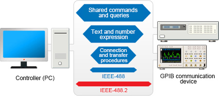
GPIB (General Purpose Interface Bus) was developed as an interface between computers and measuring instruments. It is mainly used to connect PCs and measuring instruments. GPIB was created as HP-IB, an in-house standard developed by Hewlett Packard, which was approved by the IEEE (Institute of Electrical and Electronics Engineers) and became an international standard. Many current measuring instruments support the GPIB interface as standard, and it is widely used in measurement systems using PCs and measuring instruments.
GPIB standards
GPIB standards include IEEE-488 and the higher-level protocol IEEE-488.2, which is currently mainstream. In addition to the transfer methods specified in IEEE-488, IEEE-488.2 features syntax for text data and numeric expressions, and commands and queries that can be used by all instruments. IEEE-488.2-compatible instruments can communicate with other IEEE-488.2-compliant devices and with IEEE-488 devices within the scope prescribed in IEEE-488.
Advantages of GPIB
-
GPIB employs a bus interface, and piggyback connectors make connecting and configuring devices easy. It is possible to use a single PC interface even if more devices are connected to the system in the future.
-
Handshake communication ensures highly reliable data transfer.
-
As the standard bus of the measuring instrument industry, the GPIB interface is employed by many measuring instruments, allowing users to control a variety of measuring instruments by mastering a single protocol.
-
Devices with different communication speeds can be connected. (*The whole system will be limited to the speed of the slowest device.)
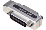 Piggy back connector
Benefits of connecting GPIB devices to a PC
The reason why the GPIB interface is still used in many measuring instruments and has been able to establish itself as the standard bus of the measuring instrument industry is due to the many advantages offered by connecting GPIB devices to a PC.
-
Automate measurement and promote labor savings by writing and executing device control programs on a PC.
-
Create a measurement system that leverages the capabilities of the PC, for example by displaying graphs and saving files of measurement data.
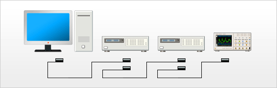
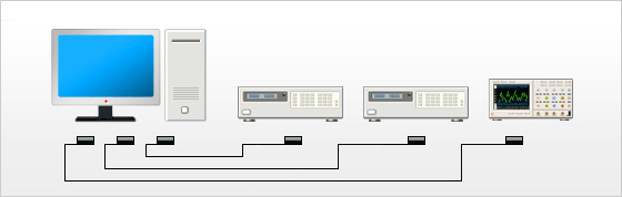
A common system setup involves connecting multiple measuring instruments to a single PC and configuring each instrument to perform automatic measurement according to a program. The acquired measurement data is then collected by the PC for analysis and display, and data retention.
 Example system of GPIB communication devices connected to a PC
Benefits of system introduction
-
Improvement of efficiency
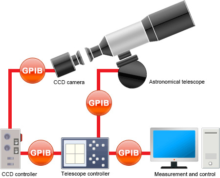
Control processes were automated, and physical and mental burden on observer was significantly reduced.
-
Observation time was significantly reduced because GPIB communication allowed image data to be imported efficiently to PC from CCD camera in block units.
Problems and points for improvement
Due to GPIB communication limitations (overall cable length of whole system), system must be operated and observations must be made near the telescope, which is inconvenient. Many researchers requested the ability to share information in real time.

At CONTEC, we can use our extensive experience in developing measurement and control equipment and network devices to solve problems like these.
Number of connections
The GPIB standard limits the number of devices that can be connected in a single system to 15 including the controller. It is not possible to connect more than this number of devices in a single system.
Connection methods
There is a high degree of freedom in device connection methods, and devices can be connected in a daisy chain or star arrangement, or in a combination of the two. Devices must not be connected in a loop arrangement.
 Daisy chain connection
 Star connection
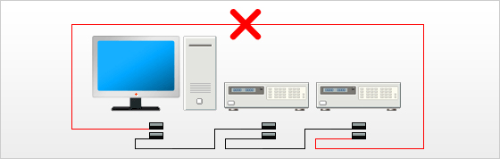 Caution: Devices must not be connected in a loop arrangement.
Cable lengths
Cables between devices may be up to 4 m long. The maximum cable length that can be used to connect devices to each other in a single system is 2 m x no. of devices or 20 m, whichever is shorter.
- Example 1: System with a total of 2 devices (1 controller + 1 GPIB communication device)
- 2 m x 2 devices < 20 m, so the maximum cable length of the whole system is 4 m.
- Example 2: System with a total of 3 devices (1 controller + 2 GPIB communication devices)
- 2 m x 3 devices < 20 m, so the maximum cable length of the whole system is 6 m.
- Example 3: System with a total of 15 devices (1 controller + 14 GPIB communication devices)
- 2 m x 15 devices > 20 m, so the maximum cable length of the whole system is 20 m.
Data transfer speed
GPIB uses eight data lines to transfer 1 byte of data at a time at a speed of up to 1 MB/s. However, many measuring instruments have a slow communication speed, and the communication speed of devices connected on the same bus will be limited to that of the slowest device.
Talkers and listeners
Of the devices connected on a bus, devices that receive data are called "listeners," while devices that send data are called "talkers."Talkers and listeners are specified by the controller. The device that manages the whole system is called the "controller", which is normally a computer (PC).
Masters and slaves
As the name suggests, the master is the device that has the power to make decisions regarding GPIB communication (command transmission, etc.,) while the slave must obey instructions issued by the master (command receipt, etc.) When configuring a system there must be one master and at least one slave. When controlling a measuring instrument, the PC acting as the controller is the master.
Device addresses
Each device connected to a GPIB system has a unique address within the system that is used to identify it. (A user-assigned address is called "my address.")A device address in a GPIB system is analogous to a phone number in the telephone system, and communication is achieved by sending and receiving data to or from the device with this number.Device addresses for the same system can be set freely from 0 to 30, but must not overlap with other addresses.
Handshake communication
A handshake is a communication method wherein a signal is sent from the sender to the receiver saying, "I'm sending data." On receiving this signal, the receiver reads data from signal lines and then sends a signal back to the sender saying, "I received the data you sent". By repeating this process, the sender and receiver transfer data while checking that it is being sent and received. Handshake communication allows GPIB to achieve highly reliable data transmission.
Roles of the controller
To prevent data from colliding, the number of devices on a GPIB bus line that can send data at any point in time is restricted to one. The device that achieves this is the controller. The controller mainly performs the operations below. If these operations are expressed in a program, it is possible to build a GPIB system that has a PC as a controller.
-
Specifies the talker.
-
Specifies listeners with respect to the talker. (Multiple devices possible.)
-
Is able to reset the system to its initial state.
-
Controls each device remotely.
-
Takes the role of responding to service requests from each device.
-
Is able to give commands to each device.
GPIB signal lines
GPIB signal lines are comprised of eight data lines, three handshake lines, and five management lines. Connector pin assignments are standardized as shown in the pinout below.It is especially important to understand the role of the management bus lines that are required when putting together a GPIB program.
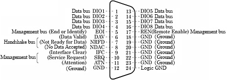 GPIB connector pinout
Management bus lines (x5)
Management bus lines are used to efficiently control each device connected to the bus line, and manage the flow of information. They play an important role in controlling GPIB devices.
- ATN(Attention)
- The ATN line is used in data mode, which is used to transfer data between devices, and command mode, which is used to send commands to each device from the controller. The ATN line indicates the current state of the data lines. The ATN line is managed by the controller. When the ATN line is low, each device is required to receive a command from the controller. If the ATN line is low, the bus is in command mode; if the line is high, the bus is in data mode (which is used for sending and receiving measurement data, etc.)
- IFC(Interface Clear)
- The controller uses the IFC line to send a signal to initialize interface functions on all devices. Each device receives this signal and resets interface functions to their initial state. However, components that are unique to each device (device functions,) such as buffer content, are not initialized. (Device function components are initialized via the device clear command or a unique device command.) The IFC signal is sent as a pulse of at least 100 μs.
- SRQ(Service Request)
- The SRQ signal is used by each controlled device to notify the controller when a process ends or an error occurs. When a device requests a service, it pulls the SRQ line low. When the controller becomes aware that the SRQ line is low, it conducts a poll to investigate which devices made the request and what kind of services they requested.
- REN(Remote Enable)
- Used to control the remote/local status of the device. The remote enable function is only available to devices with a controller function.
- EOI(End or Identify)
- To communicate, both the sender and the receiver must terminate communication (completion of sending and completion of receiving) simultaneously. When communicating binary data, the EOI signal is used to indicate the end of the data. While a delimiter code can be used for text data, it is necessary to control the end of the data via the EOI line for binary data communication.
Data lines (x8)
Data lines are used for sending multiline messages and for transferring data.
Ground lines (x8)
Signal lines other than data lines all consist of a ground line and a twisted pair. Cables and connectors used in GPIB applications are shielded, and provide excellent noise resistance.
Handshake lines (x3)
These lines are used for data line handshakes.
- DAV(Data Valid)
- Signal line that indicates that data is being sent.
- NDAC(No Data Accepted)
- Signal line that indicates that data has not been completely received.
- NRFD(Not Ready For Data)
- Signal line that indicates that devices are not completely ready to receive data.
SRQ (service requests) and polling
To control GPIB devices via a program and receive data, having an understanding of how SRQ (service requests) and polling work in addition to how management bus lines operate, will allow you to create efficient programs.
SRQ (service requests)
SRQ is a function that allows a device to send an interrupt request to the controller to let it know that an error has occurred or that the device is ready to send, and so on. If an SRQ request occurs, the SRQ line switches to true, which tells the controller that a device connected to the bus is requesting a service. However, as the controller cannot know which device sent the request based solely on the SRQ request, it conducts a poll to identify the device requesting the service and check the content of the request.
Serial poll
Serial poll is a method whereby the controller transmits an SRQ signal serially to query each device that may be requesting a service. Polled devices send a single byte of data called a "status byte" to the controller. The controller examines the status byte of each device to determine which devices have requested a service and what kind of service they have requested. Serial polls are generally the most common type of poll used.
Parallel poll
Parallel poll is a method whereby each of the eight data lines is assigned to a single device so that the controller can instantaneously determine which (of the maximum eight) devices have transmitted the SRQ signal. When a parallel poll is executed, each device transmits a 0 or 1 on its assigned data line to tell the controller whether or not it requested the service.
Status byte
Status bytes (single bytes) are output via data lines in the same way as sent and received data. When a device issues an SRQ, the 6th bit of the status byte switches to 1 (true); it switches to 0 (false) if the device is not issuing an SRQ. The remaining bits of the status byte are able to have device-dependent meanings. For example, they can notify the controller of the cause of the SRQ (measurement completed, error occurred, etc.) After being polled by the controller, the 6th bit of the status byte is reset to 0.
Interface functions
The GPIB standard separates the functions of applicable devices into interface functions and device functions. Only interface functions are specified in the standard. However, devices connected to a GPIB system do not need to have all functions implemented.
- Device functions
- Devices functions are device-dependent components that are not defined in the GPIB standard. They include device-dependent commands, device operation methods, and measurement range configuration methods.
- Interface functions
- Interface functions are defined in the GPIB standard. GPIB communication devices should be implemented with only the required interface functions.
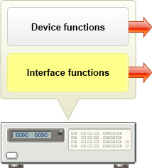 Structure of GPIB-equipped device
Messages and commands
GPIB includes a variety of standardized messages and commands, which are used to control GPIB communication devices.
Multiline interface messages
Multiline interface messages are messages (commands) that are specified by the standard for operating devices connected via GPIB. They can only be handled by the controller, and are sent using data lines (x8). Multiline interface commands include address commands and universal commands.
Device messages
Device messages are messages that are not directly related to GPIB interface functions. Examples include messages regarding measurement data such as voltages measured by a measuring instrument, and measuring instrument settings. Device messages are sent from a device that has a talker function, and are received by devices that have a listener function.
Uniline messages
Uniline messages are messages that carry meaning in a single signal line. When the line is becomes true, the command starts, and when it becomes false, the command ends.
- ATN (Attention)
- IFC (Interface Clear)
- SRQ (Service Request)
- REN (Remote Enable)
- EOI (End or Identify)
Address commands
Address commands are standardized GPIB commands only used with specific devices.
- GTL (Go To Local)
- Sets other devices to a local state.
- SDC (Selected Device Clear)
- Resets devices to their original state.
- PPC (Parallel Poll Configure)
- Configures the response bit of the parallel poll function.
- GET (Group Execute Trigger)
- Executes a trigger on a device (e.g. start measuring.)
- TCT (Take Control)
- Can appoint other devices as active controllers.
Universal commands
Universal commands are standardized GPIB commands used with all connected devices.
- LLO (Local Lock-Out)
- Disables local function of other devices.
- DCL (Device Clear)
- Initializes all devices on the bus line.
- PPU (Parallel Poll Unconfigure)
- Cancels the response bit of the parallel poll function.
- SPE (Serial Poll Enable)
- Enables serial poll mode on other devices.
- SPD (Serial Poll Disable)
- Disables serial poll mode on other devices.
- UNL (UNLISTEN)
- Puts all devices currently addressed as listeners back into idle state.
- UNT (UNTALK)
- Puts the device currently addressed as talker back into idle state.
Shared IEEE-488.2 commands
Shared commands are commands that can also be used with IEEE-488.2-compliant devices. They can control GPIB communication devices efficiently. Shared IEEE-488.2 commands and queries include *RST, *CLS, *TRG, and *IDN?