This section offers an overview and basic knowledge on motion control in an easy-to-understand way.
Contents
What is a motion control?
Motion control means “to control movement.” One distinctive example is positioning control by various motors. By giving electronic energy to a motor, a motor operates and converts it to motional energy. This technology has a key role in machining tools, robotic control, semiconductor manufacturing equipments, injection molding machines, and digital home electronics inspection machines. The equipment investment in this field is largely growing these years.
 Rotation control of conveyors
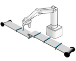
Axis control of multi-axis robot
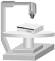 Positioning control of rotating table
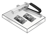 Positioning control of XY table
What is a motion control board?
Motion control board mounts functions to output pulse train at designated pulse number or frequency. It can automatically output control pulse according to motion parameters such as target position, velocity, acceleration and deceleration rate, etc. It has various limit input functions for positioning control. Motor driver controls motor itself. Motion control board outputs pulse signal for the motor driver unit and controls motor. It is connected with pulse input type stepping motors or servo motors.
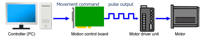
What is a motor driver unit?
A motor driver unit is a control unit to drive stepping motors and/or servo motors. Setting/acquiring control signals for this driver unit enables motor control.
What is a stepping motor?
Stepping motor is capable of high-precision positioning. By synchronizing to the input pulse, it rotates by a certain angle in stepwise. Stepping motor is operable for high-precision positioning which does not require rotation amount detection because it accurately rotates to the input pulse. General resolution is 1 step (1 pulse) = 1.8°, 0.72°, and 0.36°.
Features
- High precision positioning is possible under an open roof.
- Excellent response to starting and stopping.
- No accumulation of stopping angle accidental errors. (High-precision with an accuracy of ±0.05° for a standard stepping motor)
- High self holding power is expected even in the stop status.
- High torque is obtained at low velocity.
- Easy to maintain because the motor has a simple structure.
Step angle
Step angle is an angle that motor rotates when 1 pulse is input on motor driver by stepping motor. 1 step (1 pulse) = 1.8°, 0.72°, and 0.36° is common angle. Pulse number assigns rotation quantity and pulse frequency assigns rotation velocity.
Example) What is necessary pulse number to move carrier for 50 mm when stepping angle is 0.72°?
-
Required pulse number for motor rotation of 90°: 90 ÷ 0.72 = 125
-
Required pulse number for pulse motor round rotation (360°): 125 × 4 = 500 pulses
-
Suppose a round rotation moves carrier for 10 mm: 50 mm ÷ 10 mm = 5 rotations
-
Required movement pulse number: 500 pulses x 5 round rotation = 2500 pulses
Rotation velocity
Rotation velocity of stepping motor is exactly proportional to pulse signal velocity. Relation between rotation velocity and pulse signal is set up by the following formula. Pulse number assigns rotation quantity and pulse frequency assigns rotation velocity.
Motor rotation velocity (r/min) = step angle (°) / 360° × pulse velocity (frequency: Hz) × 60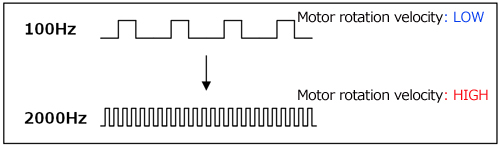
- Example) Motor velocity in case of stepping angle = 0.72°, pulse velocity = 1000 Hz
- Motor rotation velocity (r/min) = 0.72/360 × 1000 × 60 = 120 (r/min)
Losing steps
Losing steps refers to when a stepping motor cannot rotate in sync with pulses because of a rapid change in velocity (acceleration and deceleration) or an excessive load, resulting in stoppage or offset positioning. Recent stepping motor has a structure that does not generate losing steps.
What is a servo motor?
Servo motor has two types; AC servo motor and DC servo motor. Servo motors are widely used on machining tools and industrial robots at manufacturing factories. Servo motor has encoder to detect rotation angle, and high-precision positioning is done on closed loop. Our motion control boards are applicable to pulse input type servo motors.
Feature
- High speed response is expected without losing steps even at overloads or sudden pulse velocity change since it can generate large acceleration and deceleration torque.
- It can generate smooth rotation from low to high velocity and operates at low noise.
- High output is expected at small and light size
What is an encoder input?
Our motion control board mounts counter function for feedback control. By connecting to incremental encoder (UP/DOWN motion), high-precision feedback control is operable. Feedback control itself requires programming. Input circuit is compatible with two-phase (A/B phase) and single-phase (UP/DOWN). It can be used with encoders compatible with differential output, TTL level output, and open collector output.
Main application
- Pulse output from servo motor → manage/control position information
- Loosing steps detection on stepping motor
Pulse output signal/method
Our motion control board has following output types compatible to pulse train input type motor drivers.
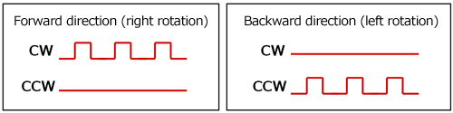
2-pulse type (independent pulse output)
Control type by emitting two independent pulse signals indicates forward (CW) and backward (CCW). CW (clockwise) indicates rotation to the right, and CCW (counter clockwise) indicates rotation to the left.
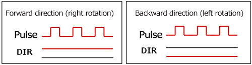
Common pulse type (directional signal output: OUT (pulse output), DIR (directional output))
Control by one pulse signal controlling travel distance and velocity, and a signal deciding rotation direction.
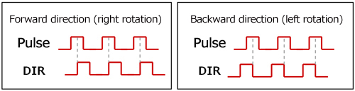
OUT (forward pulse output) signal and DIR (delay pulse output) signal type
Outputs OUT (forward pulse output) signal and DIR (delay pulse output) signal. In case the phase of DIR and OUT is +90° different, it moves (rotates) to forward (Clockwise). In case the phase of DIR and OUT is -90° different, it moves (rotates) to backward (Counter Clockwise).
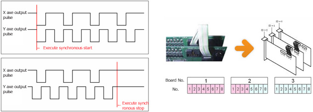
Multi-axis synchronization, inter-board multi-axis synchronization
Our motion control boards are capable of synchronizing control of inter-multi-axis synchronizing start/stop. By connecting to designated synchronizing control cable, maximum of 16 frames (128 axes) can be controlled synchronizing. For 8-axis board, grouping by 4-axis is possible.
Limit input
A function to detect stop, deceleration point, and origin of motor (carrier). It is capable of high-precision positioning control.
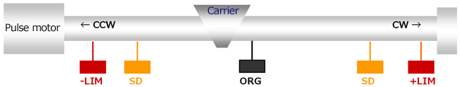
- +LIM / -LIM (direction limit): + is clockwise, - is counter clockwise
- An input signal to detect limit position. Put it at the motion limit position, for +LIM motor rotation direction is CW (clockwise), and for –LIM motor rotate direction is CCW (counter clockwise). When a carrier reaches to the point, motor immediately stops under any conditions.
As long as movement directive (order) is given to the same direction, it never moves further than this limit position. It restarts its motion (rotation) only when movement directive to opposite direction is given.
- +SD / -SD (direction slowdown): + is clockwise, - is counter clockwise
- SD is a limit input to detect the deceleration start point under high velocity rotation operation (acceleration and deceleration motion operation). A carrier under high velocity motion (transfer) starts deceleration at this position and finally stops after reaching starting velocity.
- ORG (origin limit)
- A switch input to detect origin points for standards of various motions. Setting of logic direction is possible by software. It stops on signal input by setting.
Alarm code
A driver unit can transmit alarm code at the same time as alarm signal occurrence. An alarm code indicates cause of alarm occurrence. By receiving alarm code on application, it can output (emergency) operation process according to each alarm code on the screen. Operators can conduct designated (emergency) operation quickly.
Alarm clear signal
Driver unit of servo motor and stepping motor needs to stop its motor to protect itself from overload, over voltage and over heat. In those cases, driver unit transmits alarm signal to the board (application). By receiving alarm signal, it stops movement of axis on synchronizing setting as well. When application receives alarm signal, the system needs to be disconnected for process and alarm signal needs to be canceled. In this case, it transmits alarm clear signal.
Hold off
Utilize hold off signal to sustain the hold status at positioning of stepping motor. (Automatically) turn the hold to OFF (hold off) inside board during motor movement, turn the hold ON (hold on) when motor stops.
Deviation counter clear signal
Servo motor has deviation counter inside driver unit, and it functions to count deviation between input pulse and feedback pulse. When pulse is input into driver, counter accumulates pulse (accumulated error pulse). When motor rotates, accumulated error pulse is decreased by feedback signal for positioning control so that accumulated error pulse ends in 0. In case of origin return motion, motor stops immediately at the origin detection, deviation could accumulate in the counter, and accumulated error pulse could remain. By setting deviation counter clear signal into driver unit, origin return completes.
PTP motion
PTP motion means movement between one point to the other (Point To Point). It is used for simple positioning control. Our motion control board is capable of changing stop position at desired timing even during motion. The figure on the right indicates the case of changing the target position to further during acceleration / constant velocity movement. For example, during movement from start point to the 3000-pulse point, the point can be changed to the 5000-pulse point without halting.
JOG motion
JOG motion is a transfer motion without traveling distance designation. It is used for manual motor positioning. The motor keeps operating until ±LIM signal input or stop order is given. The velocity and acceleration and deceleration time can be changed at any desired timing during operation.
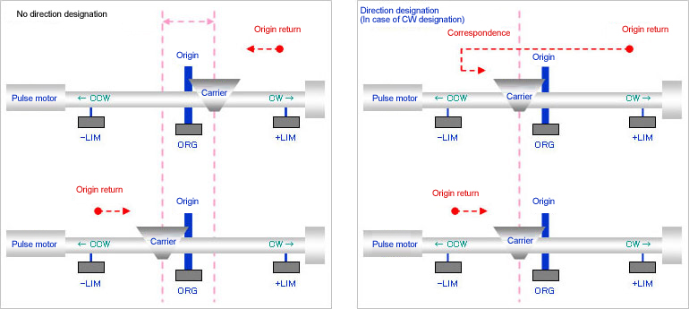
ORG motion
ORG (origin return) motion is a movement for shifting motor to the origin point. We are capable of unique origin return movement as follows. By origin return motion setting, ORG motion is set to motion type, and when movement starts, the driver automatically control until origin return completes.
Thus, origin return motion is easy without a need for creating origin return logics.
- Capable of specifying origin return end direction
- Origin limit sensors are not necessarily high accuracy sensors. Therefore, position margin error can happen between the cases of detecting limit from positive side and negative side. To solve this problem, we detect limit only from one side.
- No need for NORG (near origin)
- In case of using acceleration and deceleration movement for origin return, deceleration stop limit sensor was required near origin limit as near origin in order to stop absolutely at the origin limit. Only origin limit sensor can work as near origin as well.
 Click to enlarge
Constant velocity / straight line acceleration and deceleration / S-curve acceleration and deceleration
Constant Velocity Movement
Outputs pulse at the constant velocity (frequency). An equipment moves at the constant velocity. Sudden velocity change occurs at the start-up and stop.
Linear Acceleration/Deceleration Movement
Movement to absorb shocks at the start-up and stop by accelerating / decelerating the velocity at the constant rate at the start-up and stop. It is also called as trapezoidal velocity control.
S-curve acceleration and deceleration movement
Velocity control method further reduces the abrupt shocks on linear acceleration and deceleration movement. By reducing acceleration rate at the start-up and stop period of acceleration and deceleration, the shocks at the movement start-up and stop are diminished.
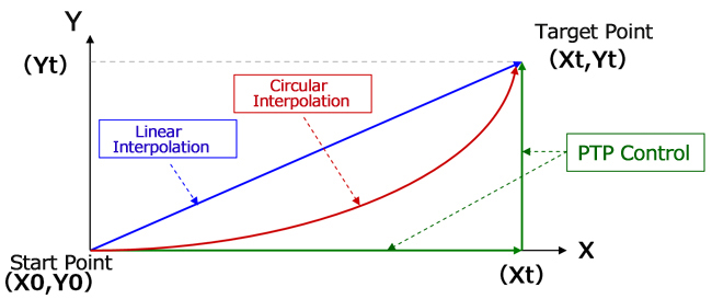
Interpolation control
Three multi-axis control types to move from start point to target point when controlling more than 2 axes.
PTP control (Point To Point)
First move the X-axis to point (Xt), then move the Y-axis to point (Yt).
Linear interpolation
Coordinate control of both the X-axis and the Y-axis, and move the to points (Xt, Yt) so that the trajectory follows a linear profile.
Circular Interpolation
Assign central coordinate of circular and target point on the circular. While synchronizing control both X-axis and Y-axis, move the points to (Xt, Yt) so that the trajectory follows profile as programmed.
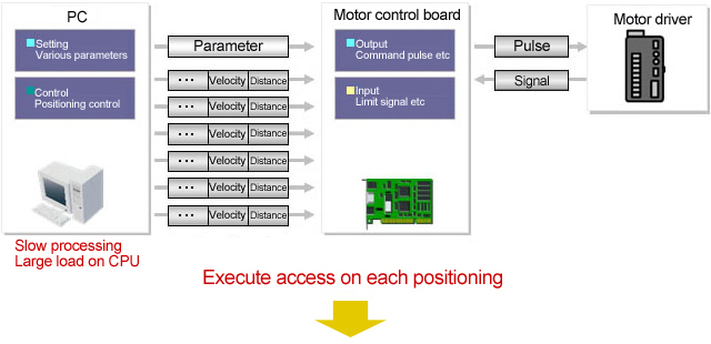
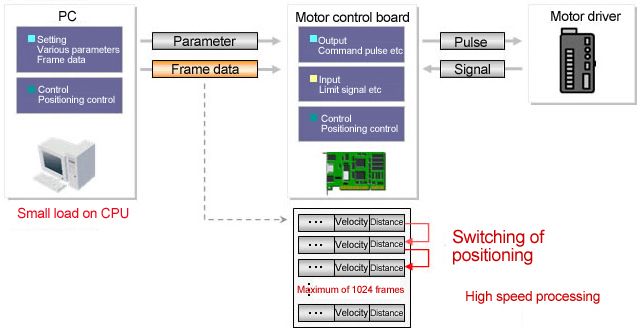
Frame (bank) memory continuous movement function
Our motion control boards deal motor movement parameter groups such as travel distance, travel velocity, acceleration and deceleration rate as one frame, and download consecutive multiple frames into onboard memory and then execute. This is a great advantage that did not exist before.
For fixed pattern motion control, high velocity control without load on CPU of PC is possible even under complicated control.
The idle time of switching to next motion is within 1μsec since continuous switching of each frame is operated on hardware.
Thus, highly efficient systems can be constructed. Continuous multi-axis interpolation control is possible by combining various interpolation controls.
Normal movement
Bank movement
General (control signal) I/O
Our motion control board mounts 7 general input (control signal input) and 3 general output (control signal output) per axis.
- ALM (input)
- Signal to detect alarm signal from motor driver unit.
- INP (input)
- Signal to detect positioning completion signal from servo driver. Outputs when deviation counter is 0. In case INP is allocated, the board does not recognize movement completion until INP turns ON.
- SD (input)
- Signal to detect a point to start deceleration.
- LTC (input)
- Signal to latch various counter values.
- PCS (input)
- Signal to input positioning control start and override target position.
- CLR (input)
- Signal to clear various counter values.
- ALMCLR: Alarm clear signal (output)
- Approve driver unit operation, reset when error occurs.
- ERC: Deviation counter clear signal (output)
- Clear accumulated error pulse.
- Various event occasions (output)
- Used when output pulse value and encoder input value coincide programmed counter value (CP1, CP2).
Automatically controls on board side by various I/O signals IN1-IN6, OUT1-OUT3.
- Example 1
- In case IN1 is set as ALM signal, when IN1 is input in signal during pulse output, board automatically stops pulse output. If IN1 is not set as ALM signal, pulse output does not stop even signal is input into IN1.
- Example 2
- When OUT1 is set as ERC signal, OUT1 automatically outputs 1 shot pulse or level signal when pulse output is completed and fixed time period passed.